Running TOS Bussard Scoops with Arduino

In the world of Star Trek, the iconic red glowing Bussard collectors, or Running TOS Bussard Scoops with Arduino, have long fascinated fans. These devices, attached to the nacelles of Starfleet vessels, are designed to collect interstellar hydrogen to fuel the ship’s engines. While the technology is purely fictional, many fans have taken to replicating these visually stunning effects for their models and displays. Using an Arduino, you can create your own Bussard scoops that mimic the mesmerizing motion and glow seen in the original Star Trek series (TOS).
Understanding the Bussard Scoop Concept
Before diving into the technicalities, it’s essential to understand what Bussard scoops are and how they are depicted in Star Trek. The Bussard collectors, named after physicist Robert W. Bussard, are envisioned as powerful magnetic fields designed to collect and funnel interstellar hydrogen into the ship’s fusion reactors. In the context of TOS, they appear as swirling, glowing red domes on the starship’s nacelles, adding to the ship’s futuristic and dynamic aesthetic.
Why Use Arduino?
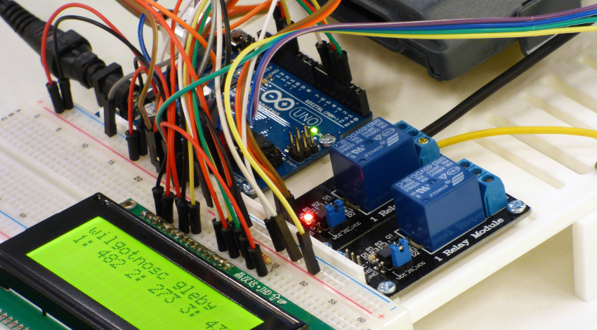
Arduino is a versatile microcontroller platform that allows hobbyists and DIY enthusiasts to create a wide range of projects. Its open-source nature and the vast community support make it an excellent choice for replicating the Bussard scoops. With Arduino, you can control LEDs, manage the lighting effects, and even add sound to your Bussard scoops, all while maintaining flexibility and customizability.
Materials Needed
To recreate the Bussard scoops using Arduino, you will need the following components:
- Arduino Uno or Nano: A microcontroller board to manage the LED effects.
- Addressable LED Strip (WS2812B or similar): These LEDs can be individually controlled to create the swirling effect.
- Red Diffuser Domes: To replicate the red glow seen on the original series.
- Power Supply (5V for Arduino and LEDs): Ensure you have a sufficient power supply to drive the LEDs.
- Wires and Connectors: For connecting the components.
- Resistors (330Ω): To protect the LEDs.
- Push Buttons or Switches: For manual control, if desired.
- Software (Arduino IDE): For programming the Arduino board.
Step-by-Step Guide
-
Set Up the Arduino Environment
- Install the Arduino IDE on your computer.
- Connect your Arduino board to your computer via USB.
-
Install Libraries
- For this project, you’ll need the FastLED or Adafruit NeoPixel library, depending on the type of LED strip you use.
- Install the library through the Arduino IDE by navigating to
Sketch -> Include Library -> Manage Librariesand searching for the appropriate library.
-
Wiring the Components
- Connect the LED strip to the Arduino. Typically, the data pin of the LED strip connects to one of the digital pins on the Arduino (e.g., pin 6).
- Attach the power and ground wires from the LED strip to the Arduino or an external power supply.
- Connect the push buttons or switches to the Arduino if you plan to add manual controls.
-
Programming the Arduino
- Open the Arduino IDE and start a new sketch.
- Include the necessary libraries at the beginning of your sketch:
cpp
CRGB leds[NUM_LEDS];
- In the
setup()function, initialize the LED strip:cppvoid setup() {
FastLED.addLeds<WS2812B, LED_PIN, GRB>(leds, NUM_LEDS);
FastLED.setBrightness(150);
}
- Create the effect in the
loop()function. For a simple swirling effect:cppvoid loop() {
for (int i = 0; i < NUM_LEDS; i++) {
leds[i] = CRGB::Red;
FastLED.show();
delay(30);
leds[i] = CRGB::Black;
}
}
- Upload the code to the Arduino board and observe the effect.
-
Testing and Calibration
- Once the code is uploaded, power the Arduino and the LED strip.
- Observe the LEDs to ensure the desired effect is achieved. You may need to adjust the delay times or the brightness settings to perfect the look.
- If you have added push buttons, program the Arduino to change the speed or pattern of the LED effects based on button presses.
-
Assembling the Bussard Scoop
- Place the LED strip inside the red diffuser dome. Ensure the LEDs are evenly spaced to create a uniform glow.
- Secure the dome to your starship model or display.
- Connect everything to a power supply and enjoy your very own Bussard scoop.
Customizing Your Bussard Scoops
One of the advantages of using Arduino is the ability to customize the effects. Here are some ideas to enhance your project:
- Color Cycling: Create a program that cycles through different colors, simulating different operational states of the Bussard scoop.
- Sound Integration: Add a sound module to play engine or space ambient sounds synchronized with the LED effects.
- Remote Control: Use an IR receiver or Bluetooth module to control the Bussard scoops remotely.
- Multiple Modes: Program different lighting modes that can be selected via push buttons or a remote.
Conclusion
Building a Bussard scoop using Arduino is a rewarding project for Star Trek fans and electronics enthusiasts alike. It combines creativity with technical skills, allowing you to bring a piece of the Star Trek universe into your own home. With the flexibility of Arduino, you can replicate the iconic glow of the TOS Bussard scoops and customize the effects to suit your personal preferences. Whether you’re enhancing a starship model or creating a standalone display, this project is sure to impress fellow fans and ignite your passion for DIY electronics.


